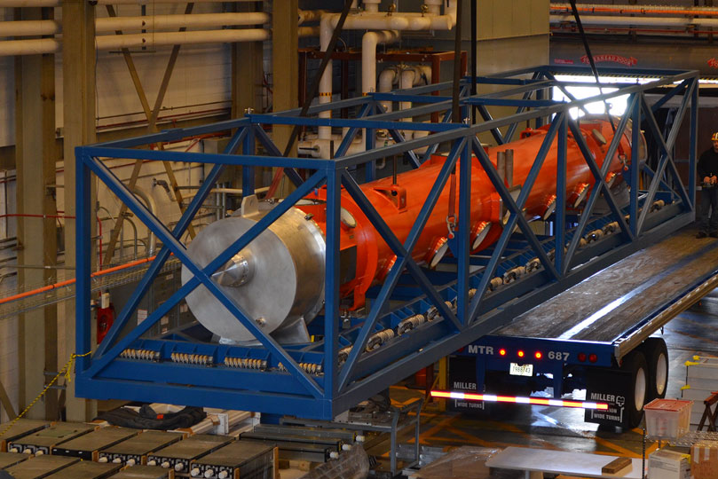
Jefferson Lab is in a partnership with Fermilab to supply all of the cryomodules that will be installed in the LCLS-II linac. The partner labs will each produce half of the needed cryomodules. The SRF Institute at Jefferson Lab will assemble and test the cryomodules using a combination of new and modified assembly tooling. This arrangement provides a unique and efficient approach that is specific to the LCLS-II project. The partner labs rely on the use of identical designs, parts and tooling interfaces. This strategy will ensure that the equivalent processes used in the fabrication of each cryomodule will yield equivalent performance, regardless of laboratory origin.
Jefferson Lab’s SRF Institute has a comprehensive infrastructure with the capability to test cavities, build cavity strings in a class 10 cleanroom environment, assemble cavity strings into cryostats, integrate all of the cryomodule parts into a cryomodule assembly and conduct performance testing of the cryomodule in the Cryomodule Test Facility (CMTF). Each cryomodule will contain eight cavities of nine cells each with coaxial power couplers operating at 1.3 GHz.
As of February 2017, Jefferson Lab completed the assembly and initial testing of the prototype cryomodule in the CMTF and began assembly activities associated with the production cryomodules. Jefferson Lab expects to complete performance testing of the last production cryomodule in the fall of 2018.
Cryomodule Procurements
The procurements of critical cryomodule components are split among the partner labs (Jefferson Lab, Fermilab and SLAC). The matrix below shows the division of procurement by partner lab. The section of components are divided between the cavity string assembly (parts that are attached to the “string” of joined cavities) and the rest of the cryomodule.
| Component | JLAB | FNAL | |
|
Cavity String |
Niobium (Production) |
X |
|
| Helium Vessels (Prototype) |
X |
||
| Cavities w/Helium Vessels -VTS Ready (Production) |
X |
||
| Cavity Feedthroughs |
X |
||
| Cavity Flanges & Assoc. Hardware/Seals (VTS & HTS compatible) |
X |
||
| Cavity String Interconnecting Bellows |
X |
||
| Cavity String Assembly Hardware & Seals |
X |
||
| SC Magnet Assembly |
X |
||
| Beam Position Monitor (BPM) |
X |
||
| Gate Valves |
X |
||
| Beamline Vac. Monitoring Manifold & Gauge |
X |
||
|
Cryomodule |
Two-phase Pipe Bellows |
X |
|
| Tuner, actuator, piezos (Prototype) |
X |
||
| Tuner, actuator, piezos (Production) |
X |
||
| Magnetic Shielding |
X |
||
| GRHP Sub-assembly |
X |
||
| Vacuum Vessel |
X |
||
| Coupler Pumping Lines & Pumps (ion+TSP) + vacuum gauges |
X |
||
| Instrumentation |
X |
||
| Liquid Level Probes & JT Valve |
X |
||
| Beamline Interconnect Parts including Aluminum Heat Shields |
X |
||
| HOM Absorber |
X |
||
| Shipping Frames & End Caps + Shock Log Devices |
X |
||
| Shipping Frames & End Caps + Shock Log Devices |
X |
Cryomodule Assembly
Cryomodules move through five workstations during the fabrication process. Each station brings the cryomodule one step closer to completion. After assembly is complete, the cryomodule makes its way to the CMTF, where the performance specifications of each cryomodule are measured.
Assembly Floor Layout
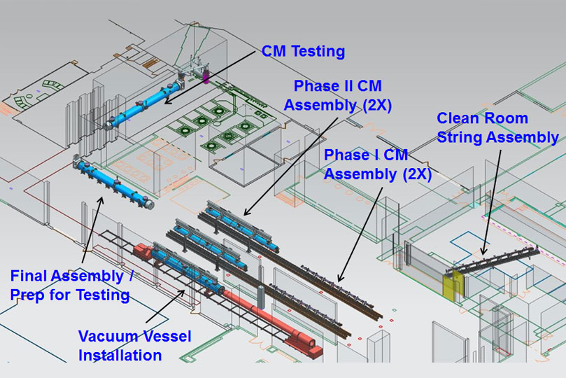
Work Station 1
Cavity String Assembly
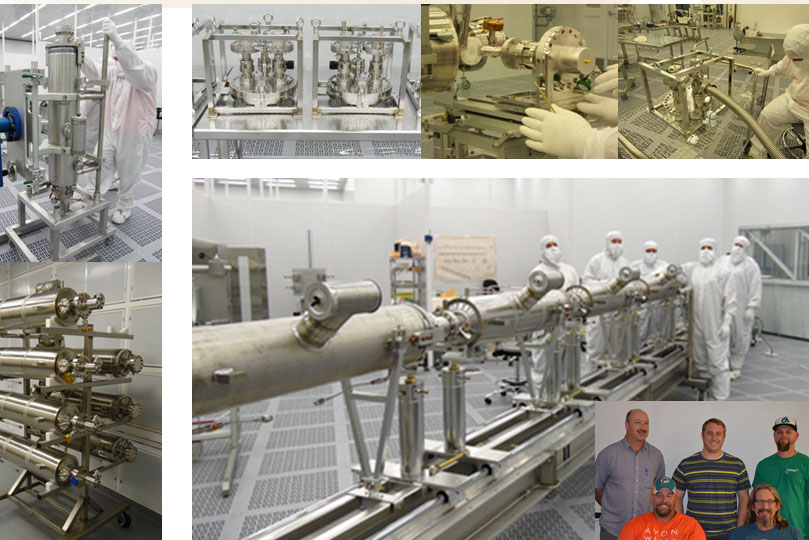
Work Station 2
Add Quadrupole, some piping and shielding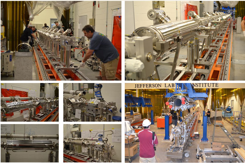
Work Station 3
Attach to GHRP, add shielding and MLI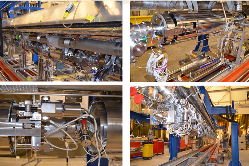
Work Station 4
Install cold mass into Vacuum Vessel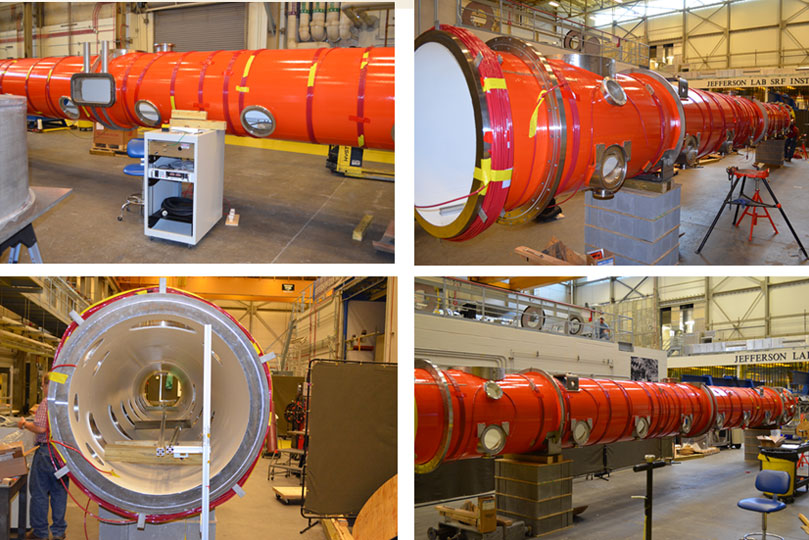
Work Station 4
Install cold mass into Vacuum Vessel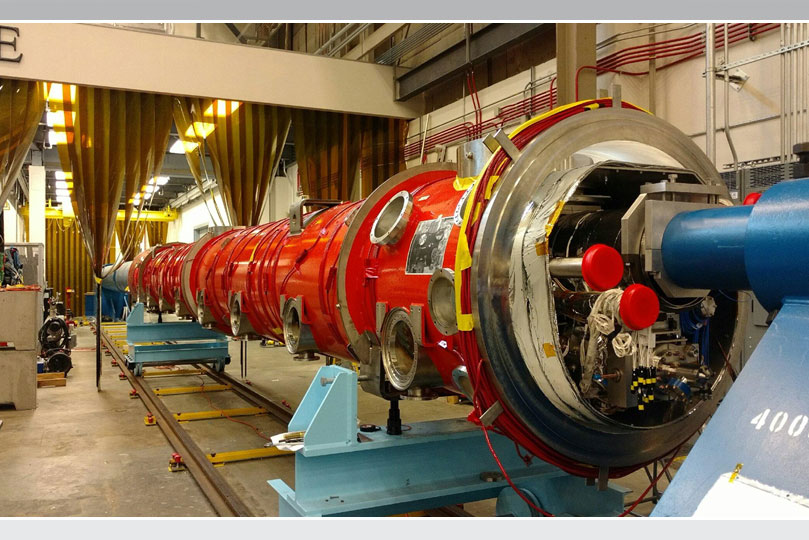
Work Station 4
Install cold mass into Vacuum Vessel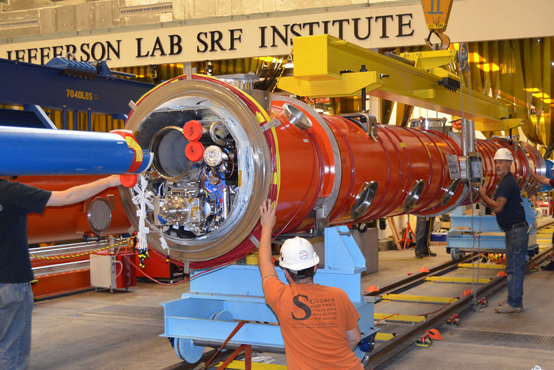
Work Station 5
Final Preparations before Testing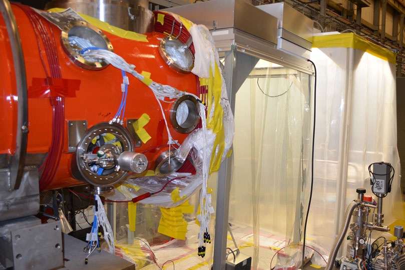
Work Station 5
Final Preparations before Testing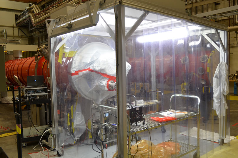
CMTF Testing
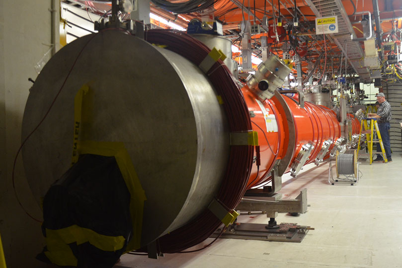
Preparing to Simulate trip to SLAC